")
- Posts: 932
- Thank you received: 564
 Question
Anschluß der HF500 Spindel
Question
Anschluß der HF500 Spindel
- Gunther57
-
- Offline
- Forum Nutzer
-

Less
More
09 Oct 2015 21:21 #25736
by Gunther57
Grössere Cu-Flächen ausfräsen geht nur mit einem Trick:
Eine extra Datei für einen grösseren Fräser (1mm oder 2mm) erstellen und dann das Ergebnis nachbearbeiten.
Gruß Gunther
Bitte keine PN. Ich bekomme keine Benachrichtigung. Besser ein e-mail.
Hardware: SC1/300, eigenbau Aduino USB V9.6
Software: Win7-64bit, Eagle, QCAD, Freecad, Estlcam V8, V9, V10
Hobby: Elektronik
;Meine DropBox
Replied by Gunther57 on topic Anschluß der HF500 Spindel
sswjs wrote: Was ich nicht gefunden hab, ist die komplette Abfräsung des nicht benötigten Kupfers. Und wenn ich den Abstand dort auf, sagen wir 30mm einstelle, macht er's zwar, aber 16(!) Stunden will ich an einer 50x80mm Leiterplatte nicht fräsen.
Grössere Cu-Flächen ausfräsen geht nur mit einem Trick:
Eine extra Datei für einen grösseren Fräser (1mm oder 2mm) erstellen und dann das Ergebnis nachbearbeiten.
Gruß Gunther
Bitte keine PN. Ich bekomme keine Benachrichtigung. Besser ein e-mail.
Hardware: SC1/300, eigenbau Aduino USB V9.6
Software: Win7-64bit, Eagle, QCAD, Freecad, Estlcam V8, V9, V10
Hobby: Elektronik
;Meine DropBox
The following user(s) said Thank You: sswjs
Please Log in or Create an account to join the conversation.
- sswjs
-

- Visitor
-

10 Oct 2015 17:48 - 10 Oct 2015 17:49 #25769
by sswjs
This message has attachments images.
Replied by sswjs on topic Anschluß der HF500 Spindel
Moin,
so, weil ich mit dem "Zeigen wir mal den Noob in mir" angefangen hab, hier mal das Leiterplattenfräsen.
Ich hoffe , ich hab hier auch gleich mal einen Tip für den einen oder anderen:
Hier sieht man, wie ich die Passerstifte für den kleinen Vakuumtisch setze. Die Paserstifte hab ich in die 6mm Spannzange der Kress eingespannt. Dann langsam auf der gewünschten Position auf die Mutter niederfahren und die Spindel dabei drehen. Geht mit etwas Übung ganz gut, nur die Referenz ist danach natürlich im Eimer. Aber wozu kann man die Referenzfahrt wiederholen...
Der exakt positionierte Vakuumtisch:
Jetzt hab ich mir einen Anschlag gefräst
was soll ich sagen: Großer Fehler, großer Fehler...
...auch das Abkleben mit einem Opferklebeband half da nichs mehr, aber der Sprühkleber hat mal wieder die Situation gerettet...
Ach ja, reichlich Testmaterial hab ich mir auch beschaft, wie man hier noch sieht.
Hier nun der erste Ausschuß:
2 Stunden Aufspannen, Planen, Bohren, Fräsen. Hätte ich nicht das Umstellen des Werkzeuges vergessen, wäre die sogar verwendbar gewesen, aber so...
Hartpapierleiterplatten auf der Kreissäge zu trennen, war auch nicht gerade eine geniale Idee von mir. Wie das ausplatzt ist irre. Also wird demnächst gefräst.
Noch einen kleinen Hinweis, für die, die es auch mal versuchen wollen: Eagle bringt von Hause aus ein Outlinewerkzeug mit. Das standartmäßig ausgegebene HPGL ist völlig ausreichend, wenn man die Bohrungen, sprich Werkzeuge, in der Datei editiert. WinPC-NC hilft dabei sehr. Das kann HPGL laden und die Werkzeuge sind auch problemlos einstellbar.
Gebohrt hab ich mit einen 0,8 und 1,3mm Hartmetallbohrer, gefräst wurde mit einem 0,3 und 1mm Strichel mit 15°.
sswjs, aka Jens
This message has attachments images.
Please log in or register to see it.
Last edit: 10 Oct 2015 17:49 by sswjs.
Please Log in or Create an account to join the conversation.
- sumstefan
-

- Offline
- Forum Nutzer
-
- Geht nicht - gibts nicht !
Less
More
- Posts: 473
- Thank you received: 161
10 Oct 2015 20:07 #25774
by sumstefan
SC 420 + Dremel 4000,Proxxon IBS/E mit JR-Kopf, Vakuumtisch: VT3040 CNC-Plus, Kärcher VC6200, Brushless-JR-Spindel im Aubau")
Flugmodellbau und alles was mir in den Sinn kommt")
This message has an attachment image.
Replied by sumstefan on topic Anschluß der HF500 Spindel
Hallo Jens, wenn du die MDF-Platte mit einer Folie anklebst , und nur die gefräste Tasche für das Fräsgut auslässt, dann reicht dein Vakuum alle mal. Das mache ich schon länger so.
Grün ist alles was mit Folie beklebt ist.
Gruß Stefan
Grün ist alles was mit Folie beklebt ist.
Gruß Stefan
SC 420 + Dremel 4000,Proxxon IBS/E mit JR-Kopf, Vakuumtisch: VT3040 CNC-Plus, Kärcher VC6200, Brushless-JR-Spindel im Aubau
Flugmodellbau und alles was mir in den Sinn kommt
This message has an attachment image.
Please log in or register to see it.
The following user(s) said Thank You: sswjs
Please Log in or Create an account to join the conversation.
- sswjs
-
- Visitor
-
10 Oct 2015 21:21 #25775
by sswjs
Replied by sswjs on topic Anschluß der HF500 Spindel
Moin,
na super, der Tip kommt hinterher...
Ne, mir ging es nicht ums zukleben, ich leg da schon Folie drauf, sondern ums Ausfräsen der MDF-Platte. Sobald man die Oberfläche verletzt, sei es durch Fräsen oder Schleifen, nimmt die Haftkraft radikal ab. Ich hab das schon am Großen bemerkt, als ich den Fräsgrad von einem stumpfen Fräser beseitigen wollte. Einmal drüber geschliffen und weg war die Haftung...
...lustiger Weise, etwas Haftkleber aus großer Entfernung aufgesprüht und das Zeuch hält bombenfest.
Morgen werd ich mal mein Glück mit den 3 übrigen Leiteplatten versuchen.
sswjs, aka Jens
Please Log in or Create an account to join the conversation.
- sumstefan
-
- Offline
- Forum Nutzer
-
- Geht nicht - gibts nicht !
Less
More
- Posts: 473
- Thank you received: 161
10 Oct 2015 22:14 - 10 Oct 2015 22:15 #25777
by sumstefan
SC 420 + Dremel 4000,Proxxon IBS/E mit JR-Kopf, Vakuumtisch: VT3040 CNC-Plus, Kärcher VC6200, Brushless-JR-Spindel im Aubau
Flugmodellbau und alles was mir in den Sinn kommt
Replied by sumstefan on topic Anschluß der HF500 Spindel
Morsche,
ich habe da volle Haftkraft. Nach dem Taschefräsen diese super gut aussaugen Sodas die Pooren nicht voll Staub sind.
Die Aussenkanten habe ich auch versiegelt.
Gude
Stefan
ich habe da volle Haftkraft. Nach dem Taschefräsen diese super gut aussaugen Sodas die Pooren nicht voll Staub sind.
Die Aussenkanten habe ich auch versiegelt.
Gude
Stefan
SC 420 + Dremel 4000,Proxxon IBS/E mit JR-Kopf, Vakuumtisch: VT3040 CNC-Plus, Kärcher VC6200, Brushless-JR-Spindel im Aubau
Flugmodellbau und alles was mir in den Sinn kommt
Last edit: 10 Oct 2015 22:15 by sumstefan.
Please Log in or Create an account to join the conversation.
- Gunther57
-
- Offline
- Forum Nutzer
-
Less
More
- Posts: 932
- Thank you received: 564
11 Oct 2015 21:43 #25795
by Gunther57
Bitte keine PN. Ich bekomme keine Benachrichtigung. Besser ein e-mail.
Hardware: SC1/300, eigenbau Aduino USB V9.6
Software: Win7-64bit, Eagle, QCAD, Freecad, Estlcam V8, V9, V10
Hobby: Elektronik
;Meine DropBox
Replied by Gunther57 on topic Anschluß der HF500 Spindel
Noch ein kleiner Tip für grössere nicht benötigte Cu-Flächen.
Diese lassen sich von der Hartpapierbasis recht einfach abziehen, einfach eine Ecke mit Skalpell lösen und kräftig ziehen. Die Kleber ist nicht so doll.
Das funktioniert nicht bei FR4 oder gleichwertiger Leiterplatten-Qualität.
Gruß Gunther
Diese lassen sich von der Hartpapierbasis recht einfach abziehen, einfach eine Ecke mit Skalpell lösen und kräftig ziehen. Die Kleber ist nicht so doll.
Das funktioniert nicht bei FR4 oder gleichwertiger Leiterplatten-Qualität.
Gruß Gunther
Bitte keine PN. Ich bekomme keine Benachrichtigung. Besser ein e-mail.
Hardware: SC1/300, eigenbau Aduino USB V9.6
Software: Win7-64bit, Eagle, QCAD, Freecad, Estlcam V8, V9, V10
Hobby: Elektronik
;Meine DropBox
Please Log in or Create an account to join the conversation.
- sswjs
-
- Visitor
-
12 Oct 2015 18:57 - 12 Oct 2015 18:57 #25827
by sswjs
This message has attachments images.
Replied by sswjs on topic Anschluß der HF500 Spindel
Moin,
so kleines Update für den Wartenden:
Ich hab vielleicht genoobt. Leiterplatten hab ich zwar gefräst, aber nun ja, alle zu klein. Hab das zu spät bemerkt und nun doch alles Leiterplattenmaterial zerschossen.
Die Woche wird es zwar neues geben, aber leider nicht vor Freitag.
Für die, die mein Teil mal nachbauen wollen, hier mal ein Foto:
Ich hab nun das Gehäuse öffters zerlegt und zusammengesetzt und die Hackenkonstruktion ist sehr gut. Hab bis jetzt keinen weggebrochen.
Und wieder zusammengesetzt. Geht wunderbar, allerdings, wer die Box zu etwas anderem als zur Stromversorgung der Stepcraft einsetzten will, wird sehr schnell bemerken, das sich die Rückwand beim Herausziehen der Stecker, sehr durchbiegt...
sswjs, aka Jens
This message has attachments images.
Please log in or register to see it.
Last edit: 12 Oct 2015 18:57 by sswjs.
Please Log in or Create an account to join the conversation.
- alpenkreuzer
-

- Offline
- Forum Nutzer
-
Less
More
- Posts: 1850
- Thank you received: 758
12 Oct 2015 19:01 #25828
by alpenkreuzer
Und wenn Du auf die Leiterplatten-Unterseite ein Stück PS in der richtigen Grösse unterklebst?
Gruss Michael
Gruss Michael
begonnen mit 420/2, Alu-Fräse "KARLA" (noch im Bau)
EstlCam mit Arduino NANO, WinPC-NC USB
Kress, QCAD, Fusion 360, Inventor, Winghelper
Replied by alpenkreuzer on topic Anschluß der HF500 Spindel
sswjs wrote: Moin,
so kleines Update für den Wartenden:
Ich hab vielleicht genoobt. Leiterplatten hab ich zwar gefräst, aber nun ja, alle zu klein. Hab das zu spät bemerkt und nun doch alles Leiterplattenmaterial zerschossen.
Und wenn Du auf die Leiterplatten-Unterseite ein Stück PS in der richtigen Grösse unterklebst?
Gruss Michael
Gruss Michael
begonnen mit 420/2, Alu-Fräse "KARLA" (noch im Bau)
EstlCam mit Arduino NANO, WinPC-NC USB
Kress, QCAD, Fusion 360, Inventor, Winghelper
Please Log in or Create an account to join the conversation.
- sswjs
-
- Visitor
-
12 Oct 2015 19:28 #25830
by sswjs
Replied by sswjs on topic Anschluß der HF500 Spindel
Moin,
Ich mach das noch einmal, dann aber richtig. Etwas Übung muss schließlich sein.
sswjs, aka Jens
Ich bau das Gehäuse aus Acryl, damit man immer meine Fehler sieht? Ne, ne.alpenkreuzer wrote: Und wenn Du auf die Leiterplatten-Unterseite ein Stück PS in der richtigen Grösse unterklebst?
Ich mach das noch einmal, dann aber richtig. Etwas Übung muss schließlich sein.
sswjs, aka Jens
Please Log in or Create an account to join the conversation.
- Pyromane
-
- Offline
- Forum Nutzer
-
Less
More
- Posts: 136
- Thank you received: 33
12 Oct 2015 21:26 - 12 Oct 2015 21:28 #25838
by Pyromane
Replied by Pyromane on topic Anschluß der HF500 Spindel
An dieser Stelle wären durchaus Kunststoff/Nylon Schrauben sinnvoll, wenn man nicht gerade die Schrauben einzeln "erden" will. Im schlimmsten Fall der Fälle könnte ein aktiver Leiter abbrechen und die blanke/leitende Schraube berühren....
Ansonsten verfolge ich dein Projekt gespannt und werde evtl. das eine oder andere für meine Schaltbox nutzen, die allerdings vom Programm gesteuert werden wird.
Ansonsten verfolge ich dein Projekt gespannt und werde evtl. das eine oder andere für meine Schaltbox nutzen, die allerdings vom Programm gesteuert werden wird.
Last edit: 12 Oct 2015 21:28 by Pyromane.
Please Log in or Create an account to join the conversation.
- sswjs
-
- Visitor
-
14 Oct 2015 20:01 #25920
by sswjs
This message has an attachment image.
Replied by sswjs on topic Anschluß der HF500 Spindel
Moin,
so der Schaltplan des Umsetzers ist fertig. Eventuell ändert sich zwar noch die Stromversorgungsbuchse, je nach dem, wie das Netzteil gepolt ist.
Mal noch bitte drüber gucken, daß ich keine groben Fehler drin hab.
Danke.
sswjs, aka jens
so der Schaltplan des Umsetzers ist fertig. Eventuell ändert sich zwar noch die Stromversorgungsbuchse, je nach dem, wie das Netzteil gepolt ist.
Mal noch bitte drüber gucken, daß ich keine groben Fehler drin hab.
Danke.
sswjs, aka jens
This message has an attachment image.
Please log in or register to see it.
Please Log in or Create an account to join the conversation.
- Gunther57
-
- Offline
- Forum Nutzer
-
Less
More
- Posts: 932
- Thank you received: 564
16 Oct 2015 21:29 #25979
by Gunther57
Bitte keine PN. Ich bekomme keine Benachrichtigung. Besser ein e-mail.
Hardware: SC1/300, eigenbau Aduino USB V9.6
Software: Win7-64bit, Eagle, QCAD, Freecad, Estlcam V8, V9, V10
Hobby: Elektronik
;Meine DropBox
Replied by Gunther57 on topic Anschluß der HF500 Spindel
Ist es gewollt?
Das Signal vom X1 pin1 wird negiert an X2 pin13 weitergegeben.
X1-1 =0V --> X2-13 =high (kenne deine Versorgungsspannung von X3 nicht)
X1-1 =high --> X2-13 =0V
Gruß Gunther
Das Signal vom X1 pin1 wird negiert an X2 pin13 weitergegeben.
X1-1 =0V --> X2-13 =high (kenne deine Versorgungsspannung von X3 nicht)
X1-1 =high --> X2-13 =0V
Gruß Gunther
Bitte keine PN. Ich bekomme keine Benachrichtigung. Besser ein e-mail.
Hardware: SC1/300, eigenbau Aduino USB V9.6
Software: Win7-64bit, Eagle, QCAD, Freecad, Estlcam V8, V9, V10
Hobby: Elektronik
;Meine DropBox
Please Log in or Create an account to join the conversation.
- sswjs
-
- Visitor
-
16 Oct 2015 22:08 #25981
by sswjs
Replied by sswjs on topic Anschluß der HF500 Spindel
Moin,
Siehe:
und
Bei der Steppi wird das Relais mit einen High-Pegel eingeschaltet, aber das Signal von der anderen Maschine ist Low-Aktiv.
Ach ja, die Spannung ist 5V vom Netzteil.
sswjs, aka Jens
Jep ist gewollt, wegen der Negation betreib ich hier doch den ganzen Aufwand.Gunther57 wrote: Ist es gewollt?
Das Signal vom X1 pin1 wird negiert an X2 pin13 weitergegeben.
Siehe:
Anha60de wrote: Zero 3 Pin 1 an HF500 Pin 13 Spindel an/aus
Zero 3 Pin 18 an HF500 Pin 7 PWM Signal
Zero 3 Pin 19 an HF500 Pin 10 Masse
und
Bei der Steppi wird das Relais mit einen High-Pegel eingeschaltet, aber das Signal von der anderen Maschine ist Low-Aktiv.
Ach ja, die Spannung ist 5V vom Netzteil.
sswjs, aka Jens
Please Log in or Create an account to join the conversation.
- sswjs
-
- Visitor
-
17 Oct 2015 20:53 #26013
by sswjs
This message has attachments images.
Replied by sswjs on topic Anschluß der HF500 Spindel
Moin,
so, Projekt >>Leiterplatten fräsen lernen<< abgeschlossen, sie sind alle gefräst und passen:
Jetzt geht's nur noch bestücken und verkabeln. Na ja, und Nachfräsen. Eine Feder hab ich mittlerweile abgebrochen.
So weiter im Thread:
Der gezeigte Schaltplan ist sicher fehlerhaft, was werden denn eigentlich für Kabel benutzt?
Das Stepcraftkabel ist mir klar, da hab ich schon die richtige Buchse gezeichnet. Für die Parallele, denk ich mal, wird ein Verlängerungskabel benutzt, also mit Stecker und Buchse. Wenn dem nicht so ist SCHREIEN...
Sollte ein Stecker-Buchse-Kabel benutzt werden, sieht der Schaltplan anders aus. Guckst du:
Wenn alles stimmt mach ich mich dann mal an eine Leiterplatte, da du das Geäuse selber fräsen willst.
sswjs, aka Jens
This message has attachments images.
Please log in or register to see it.
Please Log in or Create an account to join the conversation.
- Anha60de
-
Topic Author
- Offline
- Forum Nutzer
-
Less
More
- Posts: 99
- Thank you received: 22
18 Oct 2015 11:55 #26030
by Anha60de
Stepcraft SC420, QCAD Vollversion, Mach3 Deutsch, Laser 1000mW Blau 445nm,
Stepcraft HF500 Spindel
Replied by Anha60de on topic Anschluß der HF500 Spindel
Hallo Jens,
einfach klasse
Danke
Andrè
einfach klasse
Danke
Andrè
sswjs wrote: Moin,
so, Projekt >>Leiterplatten fräsen lernen<< abgeschlossen, sie sind alle gefräst und passen:
Jetzt geht's nur noch bestücken und verkabeln. Na ja, und Nachfräsen. Eine Feder hab ich mittlerweile abgebrochen.
So weiter im Thread:
Der gezeigte Schaltplan ist sicher fehlerhaft, was werden denn eigentlich für Kabel benutzt?
Das Stepcraftkabel ist mir klar, da hab ich schon die richtige Buchse gezeichnet. Für die Parallele, denk ich mal, wird ein Verlängerungskabel benutzt, also mit Stecker und Buchse. Wenn dem nicht so ist SCHREIEN...
Sollte ein Stecker-Buchse-Kabel benutzt werden, sieht der Schaltplan anders aus. Guckst du:
Wenn alles stimmt mach ich mich dann mal an eine Leiterplatte, da du das Geäuse selber fräsen willst.
sswjs, aka Jens
Stepcraft SC420, QCAD Vollversion, Mach3 Deutsch, Laser 1000mW Blau 445nm,
Stepcraft HF500 Spindel
Please Log in or Create an account to join the conversation.
- sswjs
-
- Visitor
-
19 Oct 2015 02:23 #26049
by sswjs
This message has attachments images.
Replied by sswjs on topic Anschluß der HF500 Spindel
Moin,
so, meine Schaltbox nähert sich der Fertigstellung, allerding werd ich das Gehäuse nochmal überarbeiten müssen, da sich das Einschrauben der Steckdosen zu einen Ausbiegen der Acrylplatte geführt hat.
Aber hier der aktuelle Stand:
so, deine Leiterplatte ist auch entwurfen:
Wenn das die richtige Buchse ist, die du auf der Acrylbox siehst, gib Bescheid
sswjs, aka Jens
This message has attachments images.
Please log in or register to see it.
Please Log in or Create an account to join the conversation.
- Anha60de
-
Topic Author
- Offline
- Forum Nutzer
-
Less
More
- Posts: 99
- Thank you received: 22
19 Oct 2015 05:48 #26054
by Anha60de
Stepcraft SC420, QCAD Vollversion, Mach3 Deutsch, Laser 1000mW Blau 445nm,
Stepcraft HF500 Spindel
Replied by Anha60de on topic Anschluß der HF500 Spindel
Hallo Jens,
das sieht ja echt gut aus. Sowie ich das sehen kann einmal Parallel 25 Pin und einmal den HF500 15Pin Stecker.
Gruß
Andrè
das sieht ja echt gut aus
Gruß
Andrè
sswjs wrote: Moin,
so, meine Schaltbox nähert sich der Fertigstellung, allerding werd ich das Gehäuse nochmal überarbeiten müssen, da sich das Einschrauben der Steckdosen zu einen Ausbiegen der Acrylplatte geführt hat.
Aber hier der aktuelle Stand:
so, deine Leiterplatte ist auch entwurfen:
Wenn das die richtige Buchse ist, die du auf der Acrylbox siehst, gib Bescheid
sswjs, aka Jens
Stepcraft SC420, QCAD Vollversion, Mach3 Deutsch, Laser 1000mW Blau 445nm,
Stepcraft HF500 Spindel
Please Log in or Create an account to join the conversation.
- sswjs
-
- Visitor
-
29 Oct 2015 07:56 #26370
by sswjs
Replied by sswjs on topic Anschluß der HF500 Spindel
Moin,
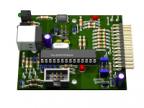
so, kleines Update zur Leiterplatte.
Die fehlende 15-polige Buchse kann ich abholen, so daß am Wochenende die Leiterplatte fertig wird und am Montag auf die Reise gehen kann. Material bis jetzt 18 Euro...
sswjs, aka Jens
PS: ...das Netzteil ist da schon dabei.
so, kleines Update zur Leiterplatte.
Die fehlende 15-polige Buchse kann ich abholen, so daß am Wochenende die Leiterplatte fertig wird und am Montag auf die Reise gehen kann. Material bis jetzt 18 Euro...
sswjs, aka Jens
PS: ...das Netzteil ist da schon dabei.
Please Log in or Create an account to join the conversation.
- sswjs
-
- Visitor
-
29 Oct 2015 18:57 #26374
by sswjs
This message has an attachment image.
Replied by sswjs on topic Anschluß der HF500 Spindel
Moin,
so heute spielen wir mal: "Such den Unterschied"
Gefunden?
Die Schaltbox besteht mittlerweile aus 5mm Lexan (Polycarbonat) und hat zusätzliche Federverbindungen, da sich das 4mm Acryl aufbog.
Bei Gelegenheit werd ich dann auch mal zeigen, wie man Teile mit variablen Plattendicken konstruiert.
Aber bis dahin...
sswjs, aka Jens
PS: Für Speedo mal die Fräsdaten
Spindel: Kress FME 1050
Drehzahl: 12.000 U/min (Rad auf der 2)
Fräser: VHM 2mm Zweischneider Fisch von Sorotec
Vorschub: 10mm/s
Zustellung: 1,25mm
auf selbstgebauten Vakuumtisch
This message has an attachment image.
Please log in or register to see it.
Please Log in or Create an account to join the conversation.
- sswjs
-
- Visitor
-
30 Oct 2015 19:10 - 30 Oct 2015 19:12 #26401
by sswjs
This message has an attachment image.
Replied by sswjs on topic Anschluß der HF500 Spindel
Moin,
so, fertig verkabelt und getestet:
Jetzt geht's an die Stepcraft...
...die DXF gibt's etwas später, ich muss die Richtigen erst mal raussuchen, hab ja nun schon die dritte Variante.
sswjs, aka Jens
PS: Material ist alles da für den Umsetzer, jetzt kann der Bau losgehen.
so, fertig verkabelt und getestet:
Jetzt geht's an die Stepcraft...
...die DXF gibt's etwas später, ich muss die Richtigen erst mal raussuchen, hab ja nun schon die dritte Variante.
sswjs, aka Jens
PS: Material ist alles da für den Umsetzer, jetzt kann der Bau losgehen.
This message has an attachment image.
Please log in or register to see it.
Last edit: 30 Oct 2015 19:12 by sswjs.
Please Log in or Create an account to join the conversation.