Benachrichtigungen
Alles löschen
Milling
15
Beiträge
4
Benutzer
0
Reactions
6,799
Ansichten

Themenstarter
I'm going crazy, I cannot figure out what is going on.
When I mill surfaces (for example to make it flat) with my 6mm 2-flute End-mill all is fine, but when I use a 6mm 1-flute End-mill to flat a surface... I get black and white stripes. Why???
Here a couple of photos (sorry for the poor quality):


When the tool is milling along the Y (i.e. increasing the Y coordinate) all is fine, the milled surface is black. When the tool turns and comes back (i.e. decreasing the y coordinate) it leaves the surface gray/white.
:huh:
I've checked the blade, it's sharp.
I've made the same test with my 1/8" 1-flute: same result.
I tried to change the deep of cut (from 0.25 mm to 1mm!): same result.
I tried different speeds: same result.
Why with two flutes end-mill the milled surface is black and with 1-flute I get a zebra? :S
I thought that maybe the shaft of the mill is not square with the surface; this means that moving the tool in one direction it cuts the surface with an angle +A, on the other hand, when moving in the opposite direction it cuts with angle -A. So part of the material goes below the bit and get compressed/melted (and the white stripes are appearing).
With the above image in my mind I've checked the axis of the spindle and regulated its perpendicularity at the best I can. It's not easy, the collar tightening the spindle doesn't allow a great degree of freedom. No way to make it perfectly square with table surface.
Anyway, after I've got an "almost" square shaft tool, I've repeated the test: no visible changes, the zebra still loves my POM.
Any idea? 🙁
SC300 + Spindle HF500 + Portalerhöhung + LinuxCNC + gsimple
Veröffentlicht : 19/05/2015 12:18 a.m.

I really do not understand the problems you have with POM. (Also refering to the other thread where you did some experiments).
I always used 2 flute endmills, for example the 2mm one with cutting depth of 2mm, 16000rpm, 6mm/s. And I don't go down in steps but cut down to the full depth of 10mm in 5 steps. No broken endmills so far.
With a 6mm cutter even if it's a one flute you should be well below 16000rpm.
Going one direction the portal speed adds to the cutter (turning) speed from perspective of the material. In the other direction the portal speed is subtracted from the cutter speed. Maybe that makes the difference.
But I think that it is really important that the endmill is perpendicular to the table. Not going down perpendicular you of course have problems in deep pockets. Maybe this is why your endmills broke in the other thread. This problem should not be fixed at the spindle/collar. The root cause is somewhere else.
How big is the overlap when cutting forth and back? I tend to use a overlap of 70% if surfaces should be nice. Meaning with each pass in one or the other direction there is only 30% of the endmill cutting material. Maybe you can play with this parameter to improve the result.
It might also be worth to try out a vacuum-cleaner. It removes the cut material which might get stuck in between of the uncut material and the cutter and increase friction (which produces more heat). Second the airflow will cool down the cutter.
SC 420 mit DIY parallel + Proxxon mit Mod + HF500 + SprintLayout + LibreCAD/QCAD + FreeCAD +WinPC starter/USB->EstlCAM + EstlCAM LPTAdapter + EstlCAM Handrad + DIY Vakuumtisch
Gruß, Andreas
Veröffentlicht : 19/05/2015 12:45 a.m.
Themenstarter
Hello MagIO2!
I would say that, in any case, 2-flutes or 1-flute (6mm or 3.172mm or 1.5mm) end-mills cuts POM like a charm! No problem about that by using my settings.
That said, current problem it's purely esthetic, the milled surface is quite planar (i.e. by touching it with your fingers you get a good feeling). What I don't like is just the "color" of that stripes.
I always used 2 flute endmills, for example the 2mm one with cutting depth of 2mm, 16000rpm, 6mm/s. And I don't go down in steps but cut down to the full depth of 10mm in 5 steps. No broken endmills so far.
1-flute mills cuts POM much better, trust me. More than this you can run the spindle at his max-speed and exploit the full torque of it.
Going one direction the portal speed adds to the cutter (turning) speed from perspective of the material. In the other direction the portal speed is subtracted from the cutter speed. Maybe that makes the difference.
Nice argument. But I think that the difference between the speed of cutting in one, or in the other, direction should be very small when compared to the turning speed of the tool (in my case between 16.000 and 20.000 rpm).
How big is the overlap when cutting forth and back? I tend to use a overlap of 70% if surfaces should be nice. Meaning with each pass in one or the other direction there is only 30% of the endmill cutting material. Maybe you can play with this parameter to improve the result.
The overlap in the above photos was 10%, when I increase it I just obtain more thin grey/white stripes. For now the unique solution I found is to force milling just in one direction (i.e. increasing Y coordinate). But this is not a real solution at all (milling became a very slow operation)
But I think that it is really important that the endmill is perpendicular to the table.
Yep! I subscribe your point of view. I think that the problem is there. Anyway I still cannot understand why a 2-flute bit doesn't suffer of the same problem. I mean... ok, maybe the tool is not perfectly perpendicular, and a 2-flute bit has 2 tips cutting the material, the 1-flute has just one. But when the rpms are so high (e.g. 20000 rpm in my case) I think that even the 1-flute bit should have enough time to cut junk material that it leaves behind.
I will make a test with an extremely slow feed-rate to see if things will go better. But I'm skeptic...
It might also be worth to try out a vacuum-cleaner. It removes the cut material which might get stuck in between of the uncut material and the cutter and increase friction (which produces more heat). Second the airflow will cool down the cutter.
Yeah, I've made this test too, no results. Same stripes even if you use a "Staubsauger" or not... 🙁
Maybe this is why your endmills broke in the other thread. This problem should not be fixed at the spindle/collar. The root cause is somewhere else.
No, I never broke an end mill until now (I'm crossing my finger). In my previous posts I just speak about broken material 'cause of excessive vibrations of the tool.
I don't know how I can make the tool more perpendicular. I've checked it with high-quality squares made in Germany. In any case I have to say that the leak in perpendicularity it's quite small. Using my eyes, I can say that the tip of the bit it's around just 0.3-0.4 mm far away from the vertical line.
I have a doubt: how I can check if the problem is the spindle itself?
I use the Stepcraft HF 500, maybe the shaft it's ok when it is stopped, but loose his perpendicularity when I start it (poor bearings?)
SC300 + Spindle HF500 + Portalerhöhung + LinuxCNC + gsimple
Veröffentlicht : 19/05/2015 2:58 p.m.
First of all: at max speed you do not have full torque. Torque is max well below full speed.
I'll give the 1-flutes a try. I just don't have much of them. The 2 flutes are maybe not perfect, but they work well enough in many different materials.
Only 10% overlap .. what's your cutting depth? One problem with one flutes is, that it is not symmetrically. If your cutting depth is too small, then the cutting edge dives into the material on one side, goes throug up to the other side, but then there is half a turn without a cutter in the material. Still the machine moves.
This puts more stress on the endmill when entering the material and leads to vibrations. From this point of view it is better to have as many flutes as possible, because then the vibrations are minimized.
Maybe in one direction those vibrations are dampened better than in the other.
I also have some black POM, maybe I'll jump in with some experiments this evening.
SC 420 mit DIY parallel + Proxxon mit Mod + HF500 + SprintLayout + LibreCAD/QCAD + FreeCAD +WinPC starter/USB->EstlCAM + EstlCAM LPTAdapter + EstlCAM Handrad + DIY Vakuumtisch
Gruß, Andreas
Veröffentlicht : 19/05/2015 3:44 p.m.
Themenstarter
Hy MagIO2,
my usual cutting depth for POM is 0.5 mm for a 6mm dia tool (0.4 mm for 1/8"=3.175mm endmill, since it is less rigid). The feed rate for 6mm endmill is usually 285 mm/sec (215 mm/sec for 1/8" endmill).
About torque I have not a clear opinion. On my thread about machining POM-Delrin Rory wrote that for HF500 holds the rule max-speed = max-torque since this motors are not like the ones for professional machining.
One problem with one flutes is, that it is not symmetrically. If your cutting depth is too small, then the cutting edge dives into the material on one side, goes throug up to the other side, but then there is half a turn without a cutter in the material. Still the machine moves.
Your explanation sounds really really good... today I will make some other tests:
1) adopt a very low feed rate (let's say half of what I use)
2) force the spindle to get inclination but in the opposite direction, to see if stripes are inverted in their position (no easy task since the collar is very rigid)
A doubt arises in my mind now, while I'm writing... I think that the particular shape of the 1-flute tool sold by cnc-plus.de can "amplify" the effect of a not perpendicular tool.
I will try to make my suspect more clear.
Here below a 1-flute very similar to mine:

And here a typical 2-flutes end mill:
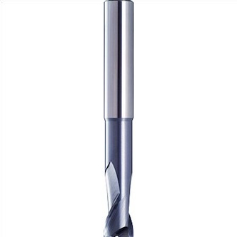
Can you see the difference? The cutter of the first tool is not "planar" (i.e. parallel to the surface). It cuts primarily by using the tip. The second has both 2 cutter planar to the surface.
I suspect that the first endmill just "scratches" the surface with the tip when the shaft is not perfectly vertical. In other words, it leaves white "rows" behind of it when moving. This happens 'cause just the tip of the cutter touches the surface.
With a traditional two flute endmill this doesn't happens 'cause the it has no prominent tip. Even if not perfectly perpendicular it always cuts, doesn't "scratches", the surface behind of it.
Can it be?
Maybe using a different end-mill the effect will disappear?
SC300 + Spindle HF500 + Portalerhöhung + LinuxCNC + gsimple
Veröffentlicht : 19/05/2015 5:39 p.m.
Machining with a 2 flute - and then with a 1 flute - with the same parameters - means you are machining at "feed per tooth rate A" (2 flute) and "feed per tooth rate A/2" with the single flute - so you will see differences.
face milling is very tricky. as any out of square-ness will show up as lines. And any differences in feeds will how up. you will do well to get a clean milled surface with the STEPPI using these sorts of cutters.
The cutter stickout you have is high also so its likely the cutters are flexing the STEPCRAFT frame.
Even we have challenges with the larger commercial routers. Face milling is tricky.
Machine at half the feedrate of the dual fluted cutter and see what happens.
First of all: at max speed you do not have full torque. Torque is max well below full speed. It would be interesting to have a torque curve for this spindle. Strictly speaking - motor torque curves will show that max power is not actually at 100% RPM but lower - However in our experience its still better to be at 70% or higher for these types of Motors.
Veröffentlicht : 20/05/2015 11:21 a.m.
Themenstarter
Reason found! B)
White strips comes out 'cause of the not perfect perpendicularity of endmill's vertical axis AND the particular geometry of the tool bit itself.
Proof
With many difficulties I have forced the spindle to have a light inclination toward the operator (that is the opposite inclination it had yesterday).
I have started to make my face milling again and... surprise! The strips are inverted! Where, yesterday, the strips was black today they are white and vice-versa.
Conclusion
The shape of the 1-flute endmill is very common for plastic-endmill. If you look at it from the top the cutter-line is not a "line" but something like a sickle ("Sichel" auf Deutsch). Furthermore, like I wrote yesterday, it is not parallel to face to be milled but has few degrees of inclination. So the way it cuts the material it's really similar to a sickle cutting the grain.
I have to admit that it cuts plastic material very well with this geometry. Much better than a traditional 2-flute for aluminum/metal. Damn! It's amazing.
Drawback: when not perfectly vertical, it will always scratch the surface behind the mill bit while it is advancing.
Solution
As I see the solution is to find a 1-flute endmill with the cutter-line (we can call it "blade") perfectly parallel to the surface to be milled. Tools by the american manufacturer Onsrud seems to have that shape, but I'm not 100% sure of this.
Another solution is to make deep pocketing with the 1-flute bit and surface finishing with a 2-flute one.
Final final final consideration
I strongly suspect that the efficiency of the tool in cutting POM/plastic like butter is also related to that light inclination of the "blade". So another 1-flute tool not producing this collateral effect could be also less efficient on plastic milling.
I also think that "sensitivity" to perpendicularity is a peculiar characteristic of all the 1-flute bits shaped in that way and is not related to the Stepcraft machine. I think that even using a professional mill-machine one can face the same problems (like Rory wrote above)
SC300 + Spindle HF500 + Portalerhöhung + LinuxCNC + gsimple
Veröffentlicht : 20/05/2015 6:53 p.m.
Themenstarter
Machining with a 2 flute - and then with a 1 flute - with the same parameters - means you are machining at "feed per tooth rate A" (2 flute) and "feed per tooth rate A/2" with the single flute - so you will see differences.
Yeah, I know that. Since many days I have adopted the 1-flute bit to half the amount of material cut and put less stress on the machine (and reduce also vibration). As you suggested, it works.
The cutter stickout you have is high also so its likely the cutters are flexing the STEPCRAFT frame.
By adoption of the right feed rate I can avoid to bend the tool or flex the machine. Obviously one has to make several tests to get the right moving speed.
First of all: at max speed you do not have full torque. Torque is max well below full speed. It would be interesting to have a torque curve for this spindle. Strictly speaking - motor torque curves will show that max power is not actually at 100% RPM but lower - However in our experience its still better to be at 70% or higher for these types of Motors.
Aaaaaaargh! :pinch:
It would be priceless to know at what rpm the max torque of the Stepcraft HF 500 is located.
Do you have the possibility to discover this important data, or even the entire chart of the torque? Please... :unsure:
SC300 + Spindle HF500 + Portalerhöhung + LinuxCNC + gsimple
Veröffentlicht : 20/05/2015 9:42 p.m.
hi,
watch in wikipedia "torque/turning moment" of an electrical motor (i used the german section) there u will find the following:
P = 2 Pi n M
if u dissolve this to M:
M = P/(2 Pi n)
and you use the known parameters:
P = 500 W,
n = 20000 rpm = 333,33 rp sec
you get the following:
M = 500 /(2 Pi 333) = 0,2389... Nm
and thats nearly the value you will find on the stepcraft homepage given for the 500 watt hf spindle. 😉
Andreas
Veröffentlicht : 20/05/2015 10:58 p.m.
I doubt that this is the correct way to calculate the torque.
The problem is, that you use max P-in in your calculation. But there is a loss in P on the way to the endmill. You have P which is converted into heat in the coils, there is some P loss because of friction... So to calculate the right torque you'd need P-out, which has to be measured. And this P-out is depending on the rpm.
So, yes, your number matches with the torque mentioned in the technical details, but my guess is that SC simply calculated it the same way. It is the torque @max voltage & @max currency and not the real max torque.
Of course I might be wrong here ...
SC 420 mit DIY parallel + Proxxon mit Mod + HF500 + SprintLayout + LibreCAD/QCAD + FreeCAD +WinPC starter/USB->EstlCAM + EstlCAM LPTAdapter + EstlCAM Handrad + DIY Vakuumtisch
Gruß, Andreas
Veröffentlicht : 20/05/2015 11:29 p.m.
Themenstarter
hi,
watch in wikipedia "torque/turning moment" of an electrical motor (i used the german section) there u will find the following:
P = 2 Pi n M
if u dissolve this to M:
M = P/(2 Pi n)
and you use the known parameters:
P = 500 W,
n = 20000 rpm = 333,33 rp sec
you get the following:
M = 500 /(2 Pi 333) = 0,2389... Nm
and thats nearly the value you will find on the stepcraft homepage given for the 500 watt hf spindle. 😉
mmmh... this means that the max torque is at the max speed? Rory said this is not true. :huh:
But the formula you used is right:
Power = Torque x 2 x Pi x Rotational_speed
so
Torque = Power / (2 x Pi x Rotational_speed)
This means that the torque is inversely proportional to rpm? What happens at 10000 rpm? The torque doubles?
SC300 + Spindle HF500 + Portalerhöhung + LinuxCNC + gsimple
Veröffentlicht : 21/05/2015 12:28 a.m.
Themenstarter
Anyway, this discussion become interesting.
Here the right article of Wikipedia for three phase asynchronous motor: Induction motor
Unfortunately, the torque of an electrical motor is not linear 'cause of construction reasons. The "poles" of the stator have fixed position and cannot apply uniform force to the rotor teeth while it is moving. More than this, all laws related to magnetic fields have a quadratic relation with the distance. To complicate things parasites inducted currents in the rotor can disturb the force. In other words: it's a bunch of formulas!!!
Anyway, exists a speed at which everything is minimized. That speed is the max-torque speed. The torque curve is something increasing slowly, reaching a max and after rapidly going down.
From what above I understand that, pushing the HF500 spindle at max speed (20000 rpm), I was doing the most wrong thing that I could do in order to get the max torque!
SC300 + Spindle HF500 + Portalerhöhung + LinuxCNC + gsimple
Veröffentlicht : 21/05/2015 1:05 a.m.
as this spindle uses a brushless motor. the rotation speed is depending on the input voltage. and the input voltage is somehow depending on the currency. therefore, if you change the speed u change the input power, too. thats what magio was talking about. we dont know if its a linar function or something else. but as a fact: these motors have a much higher efficency than the ones used in for example a "kress" spindle (1050 w input ==> 600w output).
i'm not true but, i dont think you can compare these both types 100%.
Andreas
Veröffentlicht : 21/05/2015 1:13 a.m.
Themenstarter
as this spindle uses a brushless motor.
mmmmh... I don't know... description states that the HF350/500 motor is asynchronous, while brushless motors are synchronous.
SC300 + Spindle HF500 + Portalerhöhung + LinuxCNC + gsimple
Veröffentlicht : 21/05/2015 1:59 a.m.
Themenstarter
Still waiting for Rory... it would be fantastic if he could post here the torque curve of the HF500/350... 🙁
Anyway, should be something like the one below (from wikipedia), so max torque should stay between 75% and 85% of the max speed:

SC300 + Spindle HF500 + Portalerhöhung + LinuxCNC + gsimple
Veröffentlicht : 26/05/2015 11:02 p.m.
