")
- Posts: 99
- Thank you received: 22
 Question
Anschluß der HF500 Spindel
Question
Anschluß der HF500 Spindel
- Anha60de
-
 Topic Author
- Offline
- Forum Nutzer
-

Less
More
30 Sep 2015 10:47 #25455
by Anha60de
Stepcraft SC420, QCAD Vollversion, Mach3 Deutsch, Laser 1000mW Blau 445nm,
Stepcraft HF500 Spindel
This message has attachments images.
Anschluß der HF500 Spindel was created by Anha60de
Hallo CNC`ler
ich brauche bitte euren Rat wegen einer Verdrahtung. Ich habe die HF500 Einheit und noch eine Zero 3 Steuergerät.
Ich wollte folgende Belegung zusammenschließen:
Zero 3 Pin 1 an HF500 Pin 13 Spindel an/aus
Zero 3 Pin 18 an HF500 Pin 7 PWM Signal
Zero 3 Pin 19 an HF500 Pin 10 Masse
Pinbelegung siehe Bilder. In Mach3 kann ich ja die Pins dann auswählen.
Wäre das soweit in Ordnung?
Danke
Andrè
Stepcraft SC420, QCAD Vollversion, Mach3 Deutsch, Laser 1000mW Blau 445nm,
Stepcraft HF500 Spindel
This message has attachments images.
Please log in or register to see it.
Please Log in or Create an account to join the conversation.
- Deltaflyer
-
- Offline
- Forum Nutzer
-
Less
More
- Posts: 385
- Thank you received: 142
30 Sep 2015 11:49 #25457
by Deltaflyer
Mein Tag hat 24 Stunden und reicht dies mal nicht nehm ich noch die Nacht dazu.
Replied by Deltaflyer on topic Anschluß der HF500 Spindel
Hallo André,
Was ist ein Zero 3 Steuergerät bzw. wozu wird das benötigt?
LG Stefan
Was ist ein Zero 3 Steuergerät bzw. wozu wird das benötigt?
LG Stefan
Mein Tag hat 24 Stunden und reicht dies mal nicht nehm ich noch die Nacht dazu.
Please Log in or Create an account to join the conversation.
- sswjs
-
- Visitor
-

30 Sep 2015 12:21 - 30 Sep 2015 12:21 #25459
by sswjs
Replied by sswjs on topic Anschluß der HF500 Spindel
Moin,
Pin 13 dient an der Stecraft zu Steuerung eines Relais und ist High aktiv.
Dem zu Folge würde ich auch darauf tippen, das der Pin 13 am Steuergerät einen 5V - Pegel zum Einschalten will.
Auch in der Beschreibung hier zum Anschluss des Steuergerätes findet sich kein Hinweis, das Pin 13 umgestellt wird.
sswjs, aka Jens
Nein.Anha60de wrote: Ich wollte folgende Belegung zusammenschließen:
Zero 3 Pin 1 an HF500 Pin 13 Spindel an/aus
Zero 3 Pin 18 an HF500 Pin 7 PWM Signal
Zero 3 Pin 19 an HF500 Pin 10 Masse
Pinbelegung siehe Bilder. In Mach3 kann ich ja die Pins dann auswählen.
Wäre das soweit in Ordnung?
Pin 13 dient an der Stecraft zu Steuerung eines Relais und ist High aktiv.
Dem zu Folge würde ich auch darauf tippen, das der Pin 13 am Steuergerät einen 5V - Pegel zum Einschalten will.
Auch in der Beschreibung hier zum Anschluss des Steuergerätes findet sich kein Hinweis, das Pin 13 umgestellt wird.
sswjs, aka Jens
Last edit: 30 Sep 2015 12:21 by sswjs.
Please Log in or Create an account to join the conversation.
- Anha60de
-
Topic Author
- Offline
- Forum Nutzer
-
Less
More
- Posts: 99
- Thank you received: 22
30 Sep 2015 16:02 #25467
by Anha60de
Stepcraft SC420, QCAD Vollversion, Mach3 Deutsch, Laser 1000mW Blau 445nm,
Stepcraft HF500 Spindel
This message has an attachment file.
Replied by Anha60de on topic Anschluß der HF500 Spindel
Hallo Stefan,
das ist ein Steuergerät für meine andere CNC Fräse.
Gruß
Andrè
das ist ein Steuergerät für meine andere CNC Fräse.
Gruß
Andrè
Deltaflyer wrote: Hallo André,
Was ist ein Zero 3 Steuergerät bzw. wozu wird das benötigt?
LG Stefan
Stepcraft SC420, QCAD Vollversion, Mach3 Deutsch, Laser 1000mW Blau 445nm,
Stepcraft HF500 Spindel
This message has an attachment file.
Please log in or register to see it.
Please Log in or Create an account to join the conversation.
- Anha60de
-
Topic Author
- Offline
- Forum Nutzer
-
Less
More
- Posts: 99
- Thank you received: 22
30 Sep 2015 16:06 #25468
by Anha60de
Stepcraft SC420, QCAD Vollversion, Mach3 Deutsch, Laser 1000mW Blau 445nm,
Stepcraft HF500 Spindel
Replied by Anha60de on topic Anschluß der HF500 Spindel
Hallo Jens,
vielen Dank für die Info. Ich habe meinem vorigen Poster Stefan die Zero3 PDf drangehangen. Dann wäre die HF500 somit nicht anschließbar
Gruß
Andrè
vielen Dank für die Info. Ich habe meinem vorigen Poster Stefan die Zero3 PDf drangehangen. Dann wäre die HF500 somit nicht anschließbar
Gruß
Andrè
sswjs wrote: Moin,
Nein.Anha60de wrote: Ich wollte folgende Belegung zusammenschließen:
Zero 3 Pin 1 an HF500 Pin 13 Spindel an/aus
Zero 3 Pin 18 an HF500 Pin 7 PWM Signal
Zero 3 Pin 19 an HF500 Pin 10 Masse
Pinbelegung siehe Bilder. In Mach3 kann ich ja die Pins dann auswählen.
Wäre das soweit in Ordnung?
Pin 13 dient an der Stecraft zu Steuerung eines Relais und ist High aktiv.
Dem zu Folge würde ich auch darauf tippen, das der Pin 13 am Steuergerät einen 5V - Pegel zum Einschalten will.
Auch in der Beschreibung hier zum Anschluss des Steuergerätes findet sich kein Hinweis, das Pin 13 umgestellt wird.
sswjs, aka Jens
Stepcraft SC420, QCAD Vollversion, Mach3 Deutsch, Laser 1000mW Blau 445nm,
Stepcraft HF500 Spindel
Please Log in or Create an account to join the conversation.
- sswjs
-
- Visitor
-
30 Sep 2015 16:56 #25472
by sswjs
Replied by sswjs on topic Anschluß der HF500 Spindel
Moin,
Den Schaltplan findes du hier , nur das du das Relais wegläßt und daran dein Steuergerät anschließt.
sswjs, aka Jens
Doch, wäre sie mit Hilfe eines Transistors, der als Umsetzer dient.Anha60de wrote: Dann wäre die HF500 somit nicht anschließbar
Den Schaltplan findes du hier , nur das du das Relais wegläßt und daran dein Steuergerät anschließt.
sswjs, aka Jens
Please Log in or Create an account to join the conversation.
- Anha60de
-
Topic Author
- Offline
- Forum Nutzer
-
Less
More
- Posts: 99
- Thank you received: 22
04 Oct 2015 14:38 #25586
by Anha60de
Stepcraft SC420, QCAD Vollversion, Mach3 Deutsch, Laser 1000mW Blau 445nm,
Stepcraft HF500 Spindel
Replied by Anha60de on topic Anschluß der HF500 Spindel
Hallo CNC´ler,
leider bin ich in Sachen Elektronik nicht so bewandert. Kann jemand sowas bauen?
Danke
Andrè
leider bin ich in Sachen Elektronik nicht so bewandert. Kann jemand sowas bauen?
Danke
Andrè
Stepcraft SC420, QCAD Vollversion, Mach3 Deutsch, Laser 1000mW Blau 445nm,
Stepcraft HF500 Spindel
Please Log in or Create an account to join the conversation.
- sswjs
-
- Visitor
-
04 Oct 2015 19:33 #25587
by sswjs
Replied by sswjs on topic Anschluß der HF500 Spindel
Moin,
Willst du nur den Umsetzer, soll er auf auf ne extra Leiterplatte, vielleicht mit Steckverbinder oder schon komplett im Gehäuse?
Das Pflichtenheft, also deine Anforderungen, musst du schon liefern, aber an sonsten ist das Bauen kein Problem.
sswjs, aka Jens
Ja, das kann im Prinzip jeder Elektronikamateur. Die Frage ist nur, welche Anforderungen du stellst.Anha60de wrote: ...leider bin ich in Sachen Elektronik nicht so bewandert. Kann jemand sowas bauen?
Willst du nur den Umsetzer, soll er auf auf ne extra Leiterplatte, vielleicht mit Steckverbinder oder schon komplett im Gehäuse?
Das Pflichtenheft, also deine Anforderungen, musst du schon liefern, aber an sonsten ist das Bauen kein Problem.
sswjs, aka Jens
Please Log in or Create an account to join the conversation.
- Anha60de
-
Topic Author
- Offline
- Forum Nutzer
-
Less
More
- Posts: 99
- Thank you received: 22
04 Oct 2015 21:56 #25596
by Anha60de
Stepcraft SC420, QCAD Vollversion, Mach3 Deutsch, Laser 1000mW Blau 445nm,
Stepcraft HF500 Spindel
Replied by Anha60de on topic Anschluß der HF500 Spindel
Hallo Jens,
gute Frage. Einfach den Steckverbinder. Also Anschluß des 15 Pin Steckers auf LPT. Gehäuse kann ich bei Bedarf selber bauen.
Danke
Andrè
gute Frage. Einfach den Steckverbinder. Also Anschluß des 15 Pin Steckers auf LPT. Gehäuse kann ich bei Bedarf selber bauen.
Danke
Andrè
sswjs wrote: Moin,
Ja, das kann im Prinzip jeder Elektronikamateur. Die Frage ist nur, welche Anforderungen du stellst.Anha60de wrote: ...leider bin ich in Sachen Elektronik nicht so bewandert. Kann jemand sowas bauen?
Willst du nur den Umsetzer, soll er auf auf ne extra Leiterplatte, vielleicht mit Steckverbinder oder schon komplett im Gehäuse?
Das Pflichtenheft, also deine Anforderungen, musst du schon liefern, aber an sonsten ist das Bauen kein Problem.
sswjs, aka Jens
Stepcraft SC420, QCAD Vollversion, Mach3 Deutsch, Laser 1000mW Blau 445nm,
Stepcraft HF500 Spindel
Please Log in or Create an account to join the conversation.
- sswjs
-
- Visitor
-
04 Oct 2015 23:10 #25598
by sswjs
Replied by sswjs on topic Anschluß der HF500 Spindel
Moin,
wenn du ein paar Tage warten kannst, mach ich dir 'ne Leiterplatte mit, da ich mir gerade eine neue Schaltbox baue.
Wenn die fertig ist, kann ich die ja zu dir schicken.
sswjs, aka Jens
wenn du ein paar Tage warten kannst, mach ich dir 'ne Leiterplatte mit, da ich mir gerade eine neue Schaltbox baue.
Wenn die fertig ist, kann ich die ja zu dir schicken.
sswjs, aka Jens
Please Log in or Create an account to join the conversation.
- Anha60de
-
Topic Author
- Offline
- Forum Nutzer
-
Less
More
- Posts: 99
- Thank you received: 22
05 Oct 2015 08:38 #25602
by Anha60de
Stepcraft SC420, QCAD Vollversion, Mach3 Deutsch, Laser 1000mW Blau 445nm,
Stepcraft HF500 Spindel
Replied by Anha60de on topic Anschluß der HF500 Spindel
Hallo Jens,
einfach perfekt")
Gruß
Andrè
einfach perfekt
Gruß
Andrè
sswjs wrote: Moin,
wenn du ein paar Tage warten kannst, mach ich dir 'ne Leiterplatte mit, da ich mir gerade eine neue Schaltbox baue.
Wenn die fertig ist, kann ich die ja zu dir schicken.
sswjs, aka Jens
Stepcraft SC420, QCAD Vollversion, Mach3 Deutsch, Laser 1000mW Blau 445nm,
Stepcraft HF500 Spindel
Please Log in or Create an account to join the conversation.
- sswjs
-
- Visitor
-
06 Oct 2015 17:22 - 06 Oct 2015 17:24 #25634
by sswjs
This message has an attachment image.
Replied by sswjs on topic Anschluß der HF500 Spindel
Moin,
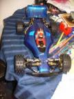
so, damit siehst, wie weit ich bin, mal ein Foto:
Zu fräsen sind noch der Boden, die Leiteplattenhalter und die Leiterplatten. Ich denke mal 2 Wochenenden werd ich noch brauchen, dann hast du auch deinen Umsetzer.
sswjs, aka Jens
so, damit siehst, wie weit ich bin, mal ein Foto:
Zu fräsen sind noch der Boden, die Leiteplattenhalter und die Leiterplatten. Ich denke mal 2 Wochenenden werd ich noch brauchen, dann hast du auch deinen Umsetzer.
sswjs, aka Jens
This message has an attachment image.
Please log in or register to see it.
Last edit: 06 Oct 2015 17:24 by sswjs.
Please Log in or Create an account to join the conversation.
- Anha60de
-
Topic Author
- Offline
- Forum Nutzer
-
Less
More
- Posts: 99
- Thank you received: 22
06 Oct 2015 17:26 #25635
by Anha60de
Stepcraft SC420, QCAD Vollversion, Mach3 Deutsch, Laser 1000mW Blau 445nm,
Stepcraft HF500 Spindel
Replied by Anha60de on topic Anschluß der HF500 Spindel
Hallo Jens,
ist echt unglaublich, einfach super. Das hätte ich überhaupt nicht auf die Reihe bekommen.
Gruß
André
ist echt unglaublich
Gruß
André
sswjs wrote: Moin,
so, damit siehst, wie weit ich bin, mal ein Foto:
Zu fräsen sind noch der Boden, die Leiteplattenhalter und die Leiterplatten. Ich denke mal 2 Wochenenden werd ich noch brauchen, dann hast du auch deinen Umsetzer.
sswjs, aka Jens
Stepcraft SC420, QCAD Vollversion, Mach3 Deutsch, Laser 1000mW Blau 445nm,
Stepcraft HF500 Spindel
Please Log in or Create an account to join the conversation.
- sswjs
-
- Visitor
-
06 Oct 2015 17:35 #25636
by sswjs
Replied by sswjs on topic Anschluß der HF500 Spindel
Moin,
sswjs, aka Jens
Keine Bange, kriegst du auch hin. Denn die kompletten Konstruktions- und Fräsdateien gibt's wenn die Schaltbox fertig ist.Anha60de wrote: ist echt unglaublich
sswjs, aka Jens
Please Log in or Create an account to join the conversation.
- sswjs
-
- Visitor
-
07 Oct 2015 13:42 #25656
by sswjs
Replied by sswjs on topic Anschluß der HF500 Spindel
Moin,
da ich gerade am Umsetzen der Leiterplatten bin, hab ich zum Anschluss eine kleine Verständnissfrage:
Willst du die HF-Spindel an einer anderen Maschine betreiben?
Wenn ja, bleit zwar die Schaltung die selbe, aber du brauchst dann zusätzlich eine Stromversorgung, da ich für den Negator eine 5V Spannung brauche. Also Batterie oder Netzteil.
Ich brauch das nämlich für meine Schaltsteckdose auch, nur das die Buchse an der Stepcraft mir alle benötigten Spannungen liefert.
sswjs, aka Jens
Please Log in or Create an account to join the conversation.
- Anha60de
-
Topic Author
- Offline
- Forum Nutzer
-
Less
More
- Posts: 99
- Thank you received: 22
07 Oct 2015 14:12 #25660
by Anha60de
Stepcraft SC420, QCAD Vollversion, Mach3 Deutsch, Laser 1000mW Blau 445nm,
Stepcraft HF500 Spindel
Replied by Anha60de on topic Anschluß der HF500 Spindel
Hallo Jens,
Willst du die HF-Spindel an einer anderen Maschine betreiben?
Ja.
Netzteil wäre super.
Danke für die Mühe.
Gruß
André
Willst du die HF-Spindel an einer anderen Maschine betreiben?
Ja.
Netzteil wäre super.
Danke für die Mühe.
Gruß
André
Stepcraft SC420, QCAD Vollversion, Mach3 Deutsch, Laser 1000mW Blau 445nm,
Stepcraft HF500 Spindel
Please Log in or Create an account to join the conversation.
- sswjs
-
- Visitor
-
07 Oct 2015 15:07 - 07 Oct 2015 15:13 #25663
by sswjs
This message has an attachment image.
Replied by sswjs on topic Anschluß der HF500 Spindel
Moin,
Ach ja, der Fortschritt:
Heute aus Unlust, was anderes zu machen, mal den Boden gefräst.
Und weil ich ja die Daten zum Schluss freigebe, also wenn alles passt, heute hier mal schon die Fräsdaten:
Fräsmotor: Kress FME 1050; Sieht ja jeder")
Drehzahl: 11.000 U/min, -> bei der Kress auf der 1 am Anschlag
Fräser: VHM 2mm Zweischneider Fisch -> von Sorotec; andere Lieferanten hab ich auch ausprobiert, keiner ging so richtig...
Zustellung: 0,5 bis 0,7 mm
Vorschub: 10mm/sek
Kühlung / Schmierung: Keine
Materal: Acryl 4mm XT(!) auf meinem selbstgebauten Vakuumtisch mit nur 13(!)mm Höhe.
...und wie man sieht produziert das gute Späne.
sswjs, aka Jens
Ok, besorg ich mit, ich denke mal für so etwas 10€ ist schon etwas brauchbares zu besorgen.Anha60de wrote: Netzteil wäre super.
Ach ja, der Fortschritt:
Heute aus Unlust, was anderes zu machen, mal den Boden gefräst.
Und weil ich ja die Daten zum Schluss freigebe, also wenn alles passt, heute hier mal schon die Fräsdaten:
Fräsmotor: Kress FME 1050; Sieht ja jeder
Drehzahl: 11.000 U/min, -> bei der Kress auf der 1 am Anschlag
Fräser: VHM 2mm Zweischneider Fisch -> von Sorotec; andere Lieferanten hab ich auch ausprobiert, keiner ging so richtig...
Zustellung: 0,5 bis 0,7 mm
Vorschub: 10mm/sek
Kühlung / Schmierung: Keine
Materal: Acryl 4mm XT(!) auf meinem selbstgebauten Vakuumtisch mit nur 13(!)mm Höhe.
...und wie man sieht produziert das gute Späne.
sswjs, aka Jens
This message has an attachment image.
Please log in or register to see it.
Last edit: 07 Oct 2015 15:13 by sswjs.
Please Log in or Create an account to join the conversation.
- sswjs
-
- Visitor
-
08 Oct 2015 15:17 - 08 Oct 2015 15:22 #25698
by sswjs
This message has attachments images.
Replied by sswjs on topic Anschluß der HF500 Spindel
Moin,
ich nochmal. Hier noch zwei Bilder vom Fortschritt:
Das ist meine temporäre Schablone für das zweiseitige Fräsen. 2mm tief ausgefräst und die Vorder- und Rückseite nur eingelegt und beim Fräsen mit der Hand niedergehalten.
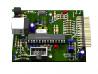
Das Gehäuse ist nun komplett. Jetzt kommt der lustige Teil. Ich will die Leiterplatten fräsen. Bei Eagle hab ich die schon erstellt, bin auch schon bis zur HPGL-Ausgabe gekommen, aber da klemmt's jetzt ein wenig. Die Bohrvorlage hab ich nicht rausgekriegt...
sswjs, aka Jens
PS: weil Alpenkreutzer damit angefangen hat: Mein Ausschuß sieht man im Hintergrund. Was fehlt sind die Testfräsungen. Und um's zu beziffern: 1 Tag testen, 2 Stunden Fräszeit und 2 Fräser hin...
...ich lern auch nur durch ausprobieren.
ich nochmal. Hier noch zwei Bilder vom Fortschritt:
Das ist meine temporäre Schablone für das zweiseitige Fräsen. 2mm tief ausgefräst und die Vorder- und Rückseite nur eingelegt und beim Fräsen mit der Hand niedergehalten.
Das Gehäuse ist nun komplett. Jetzt kommt der lustige Teil. Ich will die Leiterplatten fräsen. Bei Eagle hab ich die schon erstellt, bin auch schon bis zur HPGL-Ausgabe gekommen, aber da klemmt's jetzt ein wenig. Die Bohrvorlage hab ich nicht rausgekriegt...
sswjs, aka Jens
PS: weil Alpenkreutzer damit angefangen hat: Mein Ausschuß sieht man im Hintergrund. Was fehlt sind die Testfräsungen. Und um's zu beziffern: 1 Tag testen, 2 Stunden Fräszeit und 2 Fräser hin...
...ich lern auch nur durch ausprobieren.
This message has attachments images.
Please log in or register to see it.
Last edit: 08 Oct 2015 15:22 by sswjs.
Please Log in or Create an account to join the conversation.
- Gunther57
-
- Offline
- Forum Nutzer
-
Less
More
- Posts: 933
- Thank you received: 564
09 Oct 2015 20:51 #25733
by Gunther57
Dazu sag ich nur: Lade dir doch mal das ULP "pcb-gcode-3.6.2". Damit bekommst du getrennte Dateien in G-Code für Top, Bottom, Drill und Beschriftungen.
Gruß Gunther
Bitte keine PN. Ich bekomme keine Benachrichtigung. Besser ein e-mail.
Hardware: SC1/300, eigenbau Aduino USB V9.6
Software: Win7-64bit, Eagle, QCAD, Freecad, Estlcam V8, V9, V10
Hobby: Elektronik
;Meine DropBox
Replied by Gunther57 on topic Anschluß der HF500 Spindel
sswjs wrote: Jetzt kommt der lustige Teil. Ich will die Leiterplatten fräsen. Bei Eagle hab ich die schon erstellt, bin auch schon bis zur HPGL-Ausgabe gekommen, aber da klemmt's jetzt ein wenig. Die Bohrvorlage hab ich nicht rausgekriegt...
Dazu sag ich nur: Lade dir doch mal das ULP "pcb-gcode-3.6.2". Damit bekommst du getrennte Dateien in G-Code für Top, Bottom, Drill und Beschriftungen.
Gruß Gunther
Bitte keine PN. Ich bekomme keine Benachrichtigung. Besser ein e-mail.
Hardware: SC1/300, eigenbau Aduino USB V9.6
Software: Win7-64bit, Eagle, QCAD, Freecad, Estlcam V8, V9, V10
Hobby: Elektronik
;Meine DropBox
The following user(s) said Thank You: sswjs
Please Log in or Create an account to join the conversation.
- sswjs
-
- Visitor
-
09 Oct 2015 21:13 - 09 Oct 2015 21:14 #25735
by sswjs
This message has an attachment image.
Replied by sswjs on topic Anschluß der HF500 Spindel
Moin,
Was ich nicht gefunden hab, ist die komplette Abfräsung des nicht benötigten Kupfers. Und wenn ich den Abstand dort auf, sagen wir 30mm einstelle, macht er's zwar, aber 16(!) Stunden will ich an einer 50x80mm Leiterplatte nicht fräsen.
Mittlerweile hab ich bei dem von Eagle mitgelieferten Fräskonturen und der HPGL-Ausgabe auch die Bohrungen gefunden. Sie verstecken sich unter SP9 bis SP14, also vom 9. bis 14. Werkzeug.
Da hilft nur händisch editieren, da WinPC-NC nur bis zum 10. Werkzeug will.
Aber ich krieg das schon in Griff. (Und wenn keiner dran ist, fräs ich eben einen... )
sswjs, aka Jens
PS: Die ersten Probebohrungen mit einen 2mm HSS
Die führten prompt zur Änderung der Leiterplatte.
Danke für den Tip, aber wie das so ist, Google war schneller und ich hab das seit gestern auf den Rechner.Gunther57 wrote: Dazu sag ich nur: Lade dir doch mal das ULP "pcb-gcode-3.6.2". Damit bekommst du getrennte Dateien in G-Code für Top, Bottom, Drill und Beschriftungen.
Was ich nicht gefunden hab, ist die komplette Abfräsung des nicht benötigten Kupfers. Und wenn ich den Abstand dort auf, sagen wir 30mm einstelle, macht er's zwar, aber 16(!) Stunden will ich an einer 50x80mm Leiterplatte nicht fräsen.
Mittlerweile hab ich bei dem von Eagle mitgelieferten Fräskonturen und der HPGL-Ausgabe auch die Bohrungen gefunden. Sie verstecken sich unter SP9 bis SP14, also vom 9. bis 14. Werkzeug.
Da hilft nur händisch editieren, da WinPC-NC nur bis zum 10. Werkzeug will.
Aber ich krieg das schon in Griff. (Und wenn keiner dran ist, fräs ich eben einen...
sswjs, aka Jens
PS: Die ersten Probebohrungen mit einen 2mm HSS
Die führten prompt zur Änderung der Leiterplatte.
This message has an attachment image.
Please log in or register to see it.
Last edit: 09 Oct 2015 21:14 by sswjs.
Please Log in or Create an account to join the conversation.