")
- Posts: 267
- Thank you received: 95
 Question
Tryed to Laser Engrave, but distroyed steppy :((
Question
Tryed to Laser Engrave, but distroyed steppy :((
- dxtinct
-
 Topic Author
- Visitor
-

03 Oct 2015 18:24 #25555
by dxtinct
This message has attachments images.
Tryed to Laser Engrave, but distroyed steppy :(( was created by dxtinct
Start to feel annoyed by this product.
I have been trying to understand external signals/Sub-D 15 and instead of being able to output a TTL signal for my J Tech Prothon 2.8W laser managed to get my board destroyed.
THe documentation of stepcraft is very poor.
You can't find out how to use the outputs of this D15 conector or what to make with them..
When the smoke came out of my steppy I was measuring to find out how many volts can I get on the Pin7(found on forum that this is the Spindle PWM control) and Pin2(GND).
In the moment i have made this measurment and tryed to output the 10V for spindle PWM the smoke started coming out of my steppy.
Now I cannot reference the steppi as one IC is burned.
Does anyone if Stepcraft can sell a new signal board ?
Any ideas on hot to check for a +5V TTL signal that I could use in WINnc_PC to manage the laser burning module to be switched on/off for engraving ?
I have been trying to understand external signals/Sub-D 15 and instead of being able to output a TTL signal for my J Tech Prothon 2.8W laser managed to get my board destroyed.
THe documentation of stepcraft is very poor.
You can't find out how to use the outputs of this D15 conector or what to make with them..
When the smoke came out of my steppy
In the moment i have made this measurment and tryed to output the 10V for spindle PWM the smoke started coming out of my steppy.
Now I cannot reference the steppi as one IC is burned.
Does anyone if Stepcraft can sell a new signal board ?
Any ideas on hot to check for a +5V TTL signal that I could use in WINnc_PC to manage the laser burning module to be switched on/off for engraving ?
This message has attachments images.
Please log in or register to see it.
Please Log in or Create an account to join the conversation.
- frankjoke
-
- Offline
- Forum Nutzer
-

Less
More
03 Oct 2015 22:11 #25559
by frankjoke
Frank
Steppcraft 600/2 + HF500 + SwitchBox + Laser + Schleppmesser
Absaugung und Vakuumtisch
an Mach3 oder UCCNC mit Taster für Z-Null und Werkzeuglänge
Replied by frankjoke on topic Tryed to Laser Engrave, but distroyed steppy :((
Does not look good
I use a HF spindle and it needs two signals as well: On (actually turn right)/Off and PWM.
On/Off is on Relais1, pin 1 and PWN is on frei (Out) pin 17 on parallel.
On the connector for the spindle Relais1 is on 13 and frei (Out) on 7.
p.s.: a multi-meter helps a lot to check what's going on in the signals...
Frank
Steppcraft 600/2 + HF500 + SwitchBox + Laser + Schleppmesser
Absaugung und Vakuumtisch
an Mach3 oder UCCNC mit Taster für Z-Null und Werkzeuglänge
Please Log in or Create an account to join the conversation.
- dxtinct
-
Topic Author
- Visitor
-
03 Oct 2015 22:54 #25561
by dxtinct
Replied by dxtinct on topic Tryed to Laser Engrave, but distroyed steppy :((
hmm
so you suggest that I should use wire 13 , and wire 7 to have a ttl signal of on / off for starting stopping the j tech photonics laser ?
As i remeber i was using the multimeter and was checking in that moment the signal betweeen wire 2 (gnd) and wire 13 (relay1).... but just saw some white smoke coming from below the steppy bed..
Please Log in or Create an account to join the conversation.
- frankjoke
-
- Offline
- Forum Nutzer
-
Less
More
- Posts: 267
- Thank you received: 95
04 Oct 2015 00:45 #25564
by frankjoke
Frank
Steppcraft 600/2 + HF500 + SwitchBox + Laser + Schleppmesser
Absaugung und Vakuumtisch
an Mach3 oder UCCNC mit Taster für Z-Null und Werkzeuglänge
Replied by frankjoke on topic Tryed to Laser Engrave, but distroyed steppy :((
Be careful,
different potentials could cause additional problems.
No glue which Laser you want to power (was thinking myself as well to make such a test on Laser) but your chip did not like it.
Do you control power of laser with PWM?
different potentials could cause additional problems.
No glue which Laser you want to power (was thinking myself as well to make such a test on Laser) but your chip did not like it.
Do you control power of laser with PWM?
Frank
Steppcraft 600/2 + HF500 + SwitchBox + Laser + Schleppmesser
Absaugung und Vakuumtisch
an Mach3 oder UCCNC mit Taster für Z-Null und Werkzeuglänge
Please Log in or Create an account to join the conversation.
- dxtinct
-
Topic Author
- Visitor
-
04 Oct 2015 09:56 #25568
by dxtinct
Replied by dxtinct on topic Tryed to Laser Engrave, but distroyed steppy :((
Frank I didn't manage nothing.
Just when I was about to simulate spindle speed the board got a short from my test and was gone.
I will repair or by new electronic board and ... will try again to measure between wire 13 and wire 7 as you suggested.
I need a ttl high signal for laser on and ttl low signal for laser off. I don't understand from the documentation of stepcraft what it means relay1.
You can't get a signal just from one wire.. it needs to be something you measure from wire 2 and relay wire so that you see a +5v signal .. to know when to start laser..
Anywayz.
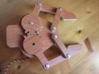
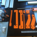
here is my project.. and J-head laser adaptor for stepcraft :
http://www.thingiverse.com/thing:1051719
Just when I was about to simulate spindle speed the board got a short from my test and was gone.
I will repair or by new electronic board and ... will try again to measure between wire 13 and wire 7 as you suggested.
I need a ttl high signal for laser on and ttl low signal for laser off. I don't understand from the documentation of stepcraft what it means relay1.
You can't get a signal just from one wire.. it needs to be something you measure from wire 2 and relay wire so that you see a +5v signal .. to know when to start laser..
Anywayz.
here is my project.. and J-head laser adaptor for stepcraft :
http://www.thingiverse.com/thing:1051719
Please Log in or Create an account to join the conversation.
- Turtleman
-

- Offline
- Forum Nutzer
-
Less
More
- Posts: 209
- Thank you received: 95
04 Oct 2015 10:15 #25569
by Turtleman
Replied by Turtleman on topic Tryed to Laser Engrave, but distroyed steppy :((
If you want to desolder the ic and you don't have any desoldering tool (think so), you can first cut off all pins with a sharp cutter just where they came out of the ic. This must be done verry carefully pin by pin, so that you don't cut into the board and don't bring to much force into the soldered pins. After that you can pick of the ic body and desolder all pins. Clean all pins befor soldering the new ic.
I think the ic will be the only destroyed part. Hope so. Good luck.
I think the ic will be the only destroyed part. Hope so. Good luck.
Please Log in or Create an account to join the conversation.
- jvalencia
-
- Offline
- Forum Nutzer
-
Less
More
- Posts: 152
- Thank you received: 97
04 Oct 2015 10:22 #25571
by jvalencia
The PWM signal is 0-5V.
Any of the Relays can be used to switch on/off your laser control unit, just configure your software properly and you're done.
Stepcraft 2 840
Kress 800 FME
UCCNC + UC100
V-Carve + QCad
Replied by jvalencia on topic Tryed to Laser Engrave, but distroyed steppy :((
dxtinct wrote: When the smoke came out of my steppy
The PWM signal is 0-5V.
Any of the Relays can be used to switch on/off your laser control unit, just configure your software properly and you're done.
Stepcraft 2 840
Kress 800 FME
UCCNC + UC100
V-Carve + QCad
The following user(s) said Thank You: ThomasDbg
Please Log in or Create an account to join the conversation.
- dxtinct
-
Topic Author
- Visitor
-
04 Oct 2015 10:43 #25573
by dxtinct
Replied by dxtinct on topic Tryed to Laser Engrave, but distroyed steppy :((
Hey guys I have al tools needed. The IC destroyed is only 0.5$.. and will replace it this week.
What I don't understand from Stepcraft.. is how this signal is 0-5v vhen in the Win Nc-PC on the Special Function Menu/ Signals Test section you can simulate an output of the signals and Spindle Speed is displayed as being 0-10V.
So .. because this instrcution in the Stepcraft site/docmentation is so poor everyone thinks and suggest different things.. but No one I see can explain exact from where to take the TTL signal and how to make it be on/off using gcodes ?
I mean what gcodes should be used to turn on/off he relay 1 and again what 2 whres are needed to connect to make relay 1 be on/off for a certain G code so that you observe on the multimeter a high/low ttl signal ?
I have followed the below post and indication in the process of destroing my steppi, but that was probably my fault.. as some other cables could have been touching maybe :
"
Rory wrote:
Very nice!!! out of interest - where exactly is that pin for PWM coming from? Through the SC card? Or via external source before going into main card?
The pin for the PWM is coming from the driver which came with the spindle, which is connected to the Sub-D 15 on the back of the stepcraft machine and the pin layouts I got from the Operating Instruction manual page 16.
I'm using relay 1(pin 13 on Sub-D 15) and a ground pin (pin 2 on Sud-D 15).
"
Please Log in or Create an account to join the conversation.
- Rory
-
- Offline
- Forum Nutzer
-
Less
More
- Posts: 383
- Thank you received: 147
08 Oct 2015 10:40 - 08 Oct 2015 10:41 #25689
by Rory
Replied by Rory on topic Tryed to Laser Engrave, but distroyed steppy :((
You need signal and ground for a logic change.
you need the signal change going from low 0V to high 5V relative to the TTL Gnd potential. This allows a relay to be used or logic to be exchanged.
in this case the M03 spindle on / off function.
always always always try with a multimeter / scope and understand whats happening before you connect /short... all it takes are a small short and you blow something up.
However - for connection of the laser - I suggest you used a controller that allows other outputs. So connect an output to the Steppi for control - Dsub 25Pin - and then connected another output to your laser device.
we have done something like this with a UC300 and UCCNC. Not sure about winPC
The STEPCRAFT card is not documented in a way that is designed to connect to an external laser as its not designed like this. its designed to be used with the STEPCRAFT items like the printer and spindle. If you go and connect other systems to the boards outputs you risk what has happened here.
also - M03 and on / off simply treats the laser like a spindle - really you need high quality raster PWM signal for proper laser workings. which cannot be achieved on current setup. you can achieve on / off and with some work analogue control of spindle speed with the PWM signal but this is quite advanced.
Last edit: 08 Oct 2015 10:41 by Rory.
Please Log in or Create an account to join the conversation.
- dxtinct2
-
- Visitor
-
08 Oct 2015 22:03 #25708
by dxtinct2
Replied by dxtinct2 on topic Tryed to Laser Engrave, but distroyed steppy :((
Thank you Rory.
I can confirm that HC244 was replaced and steppy is not back alive.
I will continue making the test with Relay(wire 13+wire 2), to understand how I can generate the M03 and M05 in the g-code.
Actually I use Estlcam as it is quite a powerfull software.
Maybe the Programmer from Estlcam can come up with some script as well to generate this gcode.
I have seen as well that J tech laser offers a script under inkscape to generate the Gcode for laser control.
I will return with new info of my findings once I will manage to engrave succesfully something with the 2.8W laser.
Thanks all.
Please Log in or Create an account to join the conversation.
- dxtinct
-
Topic Author
- Visitor
-
12 Oct 2015 22:45 #25842
by dxtinct
This message has an attachment image.
Replied by dxtinct on topic Tryed to Laser Engrave, but distroyed steppy :((
Ok thanks all for the reply.
I finally made it work.
I can tell anyone the following :
Use D15 connector and wire2 (GND) and wire 13(Relay 1) as mentioned in so many treads.
The on/off signal output by M03 and M05 will be a PWM 0-5V.
I personally have used aspire + WinNC-PC (USB or professional no matter).
I have created the drawing in Vector Aspire 4.
I have output the code in WINncPC mode but edited so that there is no movement n Z but only Laser ON/OFF.
Attached a short clip of the engraving and the file I made for being used with WinNC-PC.
My first Laser engrave on youtube !!
This message has an attachment image.
Please log in or register to see it.
Please Log in or Create an account to join the conversation.
- dxtinct
-
Topic Author
- Visitor
-
12 Oct 2015 22:47 #25843
by dxtinct
Replied by dxtinct on topic Tryed to Laser Engrave, but distroyed steppy :((
My WinPC-NC_Laser_mm.pp file, to be used for export from vectric aspire to winNC-PC.
Copy paste the below text in a WinPC-NC_Laser_mm.pp file that will be your Custom Post processor for laser cutting")
+================================================
+ WinPC-NC - Laser mm - machine output configuration file
+
+================================================
+
+ History
+
+ Who When Ver What
+ ======== ========== === =======
+ RK 2007-12-05 V1.0 Coolant Output
+ SPRS 2007-12-06 v1.1 Units mm/s Pathname
+ Documentation Extended.
+ RK 2007-11-21 Documentation of the code implemented
+ SPRS 2007-10-28
+ Mark 2008-05-13 Added Arcs
+ Mark 2008-06-18 Added initial Move to X & Y Home following
+ Move to Z Home.- Requested by John McKinnon
+
+================================================
POST_NAME = "WinPC-NC - Laser mm (*.nc)"
FILE_EXTENSION = "nc"
UNITS = "MM"
+
+ Line terminating characters
+
LINE_ENDING = "[13][10]"
+
+ Block numbering
+
LINE_NUMBER_START = 0
LINE_NUMBER_INCREMENT = 1
LINE_NUMBER_MAXIMUM = 999999
+================================================
+
+ Formating for variables
+
+================================================
VAR LINE_NUMBER = [N|A|N|1.0]
VAR SPINDLE_SPEED = [S|A|S|1.0]
VAR FEED_RATE = [F|C|F|1.1|0.01666]
VAR CUT_RATE = [FC|A||1.0|0.0166]
VAR PLUNGE_RATE = [FP|A||1.0|0.0166]
VAR X_POSITION = [X|C|X|1.3]
VAR Y_POSITION = [Y|C|Y|1.3]
VAR Z_POSITION = [Z|C|Z|1.3]
VAR ARC_CENTRE_I_INC_POSITION = [I|A|I|1.3]
VAR ARC_CENTRE_J_INC_POSITION = [J|A|J|1.3]
VAR X_HOME_POSITION = [XH|A|X|1.3]
VAR Y_HOME_POSITION = [YH|A|Y|1.3]
VAR Z_HOME_POSITION = [ZH|A|Z|1.3]
+================================================
+
+ Block definitions for toolpath output
+
+================================================
+
+ Commands output at the start of the file
+
begin HEADER
"( Filename: [TP_FILENAME])"
"[N] G17"
"[N] G90"
"[N] G71"
+
+ Commands output for Plunge Moves
+
begin PLUNGE_MOVE
"[N]M03"
+
+ Commands output for Retract Moves
+
begin RETRACT_MOVE
"[N]M05"
+
+ Commands output for rapid moves
+
begin RAPID_MOVE
"[N] G00 [X] [Y] M09"
+
+ Commands output for the first feed rate move
+
begin FIRST_FEED_MOVE
"[N] G01 [X] [Y] [F] M07"
+
+ Commands output for feed rate moves
+
begin FEED_MOVE
"[N] G01 [X] [Y]"
+
+ Commands output for the first clockwise arc move
+
begin FIRST_CW_ARC_MOVE
"[N] G02 [X] [Y] [J] [F] M07"
+
+ Commands output for clockwise arc move
+
begin CW_ARC_MOVE
"[N] G02 [X] [Y] [J]"
+
+ Commands output for the first counterclockwise arc move
+
begin FIRST_CCW_ARC_MOVE
"[N] G03 [X] [Y] [J] [F] M07"
+
+ Commands output for counterclockwise arc move
+
begin CCW_ARC_MOVE
"[N] G03 [X] [Y] [J]"
begin FOOTER
"(
)"
"( Program End )"
"(
)"
"[N] G00 [ZH]"
"[N] M05"
"[N] M09"
"[N] M30"
Copy paste the below text in a WinPC-NC_Laser_mm.pp file that will be your Custom Post processor for laser cutting
+================================================
+ WinPC-NC - Laser mm - machine output configuration file
+
+================================================
+
+ History
+
+ Who When Ver What
+ ======== ========== === =======
+ RK 2007-12-05 V1.0 Coolant Output
+ SPRS 2007-12-06 v1.1 Units mm/s Pathname
+ Documentation Extended.
+ RK 2007-11-21 Documentation of the code implemented
+ SPRS 2007-10-28
+ Mark 2008-05-13 Added Arcs
+ Mark 2008-06-18 Added initial Move to X & Y Home following
+ Move to Z Home.- Requested by John McKinnon
+
+================================================
POST_NAME = "WinPC-NC - Laser mm (*.nc)"
FILE_EXTENSION = "nc"
UNITS = "MM"
+
+ Line terminating characters
+
LINE_ENDING = "[13][10]"
+
+ Block numbering
+
LINE_NUMBER_START = 0
LINE_NUMBER_INCREMENT = 1
LINE_NUMBER_MAXIMUM = 999999
+================================================
+
+ Formating for variables
+
+================================================
VAR LINE_NUMBER = [N|A|N|1.0]
VAR SPINDLE_SPEED = [S|A|S|1.0]
VAR FEED_RATE = [F|C|F|1.1|0.01666]
VAR CUT_RATE = [FC|A||1.0|0.0166]
VAR PLUNGE_RATE = [FP|A||1.0|0.0166]
VAR X_POSITION = [X|C|X|1.3]
VAR Y_POSITION = [Y|C|Y|1.3]
VAR Z_POSITION = [Z|C|Z|1.3]
VAR ARC_CENTRE_I_INC_POSITION = [I|A|I|1.3]
VAR ARC_CENTRE_J_INC_POSITION = [J|A|J|1.3]
VAR X_HOME_POSITION = [XH|A|X|1.3]
VAR Y_HOME_POSITION = [YH|A|Y|1.3]
VAR Z_HOME_POSITION = [ZH|A|Z|1.3]
+================================================
+
+ Block definitions for toolpath output
+
+================================================
+
+ Commands output at the start of the file
+
begin HEADER
"( Filename: [TP_FILENAME])"
"[N] G17"
"[N] G90"
"[N] G71"
+
+ Commands output for Plunge Moves
+
begin PLUNGE_MOVE
"[N]
+
+ Commands output for Retract Moves
+
begin RETRACT_MOVE
"[N]
+
+ Commands output for rapid moves
+
begin RAPID_MOVE
"[N] G00 [X] [Y] M09"
+
+ Commands output for the first feed rate move
+
begin FIRST_FEED_MOVE
"[N] G01 [X] [Y] [F] M07"
+
+ Commands output for feed rate moves
+
begin FEED_MOVE
"[N] G01 [X] [Y]"
+
+ Commands output for the first clockwise arc move
+
begin FIRST_CW_ARC_MOVE
"[N] G02 [X] [Y] [J] [F] M07"
+
+ Commands output for clockwise arc move
+
begin CW_ARC_MOVE
"[N] G02 [X] [Y] [J]"
+
+ Commands output for the first counterclockwise arc move
+
begin FIRST_CCW_ARC_MOVE
"[N] G03 [X] [Y] [J] [F] M07"
+
+ Commands output for counterclockwise arc move
+
begin CCW_ARC_MOVE
"[N] G03 [X] [Y] [J]"
begin FOOTER
"(
)"
"( Program End )"
"(
)"
"[N] G00 [ZH]"
"[N] M05"
"[N] M09"
"[N] M30"
Please Log in or Create an account to join the conversation.
- diyworkbench
-
- Offline
- Forum Nutzer
-
Less
More
- Posts: 1
- Thank you received: 0
21 May 2016 01:48 - 21 May 2016 01:49 #34300
by diyworkbench
Replied by diyworkbench on topic Tryed to Laser Engrave, but distroyed steppy :((
Hey guys sorry to wake up the old post, but I seem to hit a wall here. I try go get a DVD Laser 650nm red approx. 100mA working with my steppy.
This is the driver from sparkfun I want to use: https://www.sparkfun.com/datasheets/Components/General/TTL-Laser.pdf
If I'm correct I connect the Aux1 Line to the steppy DB15 Pin 13 (+5V) and Aux2 to Pin 2 (GND).
Since the power supply (12V DC) for my laser comes from an other source than the steppy, they (might) have a different GND potential (Stepcraft PIN2 and VCC external GND).
Do i fry my board by that or will the 10K resistor make sure that does not happen? Or should I solder an other Z-Diode between the JP1 PIN 2 (SC GND) and Pin 3 (External GND) just to be sure there won't be sparks?
Thanks for your help.
Last edit: 21 May 2016 01:49 by diyworkbench.
Please Log in or Create an account to join the conversation.